Wednesday, October 21, 2009

VLAN Configuration Page 1

A step by step tutorial showing how to configure VLAN - alongwith screenshots"
Madhans Tutorials : VLAN for absolute Beginners

Objectives:

    • What is VLAN?
    • How VLAN can improve the LAN bandwidth?
    • How VLAN introduces security in a LAN network?
    • How to configure a Cisco 2950 switch for VLAN?
    • What is the difference between Access port and Trunk Port?
    • List of video tutorials giving insight into VLAN concepts.

What is VLAN?

VLAN stands for Virtual Local Area Network. VLAN is used for segmenting a LAN network. A VLAN is defined as a broadcast domain within a switched network.

The following images may give an idea about VLAN. Note : VLAN is just a software configuration. No special hardwares are needed...

Why Should I segment my LAN network?

• By segmenting, you create more broadcast domains and you get more bandwidth. • Additional security by isolating users according to work groups, department differentiation or even application usage without worrying about the physical location of the hosts.

  • Reduction in virus attacks: A virus in a computer can attack all other computers in its broadcast domain very easily. By reducing the number of machines in a broadcast domain, virus risk is also reduced. • Deployment flexibility based upon job function rather than physical placement

How segmenting can increase the bandwdith?

Each VLAN consists of a separated broadcast domain. Which means that only ports belonging to a specific VLAN share broadcasts eliminating unnecessary traffic from flooding the entire network; hence improving the overall bandwidth of the LAN. Moreover, number of messages that are to be processed by the machines are also reduced saving the valuable processor time..

The following screenshot shows a number of arp broadcast messages occupying the LAN bandwidth.


screen capture of broadcast messages

How to configure VLANs in aCisco 2950 switch?

cisco 2950 switch front and rear view
cisco 2950 switch checking the existing configuration
Cisco conguration showing the existing ports connected to VLAN 1. Note: VLAN1 is the Default VLAN, which means, even before your configure a switch, it exists by default.

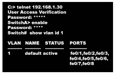
Configuration commands for a cisco switch.

screenshot showing how to configure a vlan
A Screenshot showing how to configure VLAN.

What is the Difference between "acess mode" and "trunk mode"? Have a look at the above configuration example. In this Configuration, “access mode” is used. Switch ports run in either access or trunk mode. In access mode, the interface belongs to one and only one VLAN. Normally a switch port in access mode attaches to an end user device or a server. The frames transmitted on an access link look like any other Ethernet frame.

“Trunks” on the other hand, multiplex traffic for multiple VLANs over the same physical link. Trunk links usually interconnect switches. Trunks encapsulate Ethernet frames with other information to support multiplexing.

How to configure the trunk port? SwitchA(config)#interface 0/1 SwitchA(config-if)#switchport trunk encapsulation dot1q SwitchA(config-if)#switchport trunk allowed vlan 1,2,4 SwitchA(config-if)#switchport mode trunk


How to confgure the Router?

Router(config-if)#no ip address (remove ip address in this interface)

Router(config-if)#no shutdown

Note: We are going to give different ip addresses to each sub interfaces,that is why we removed the above ip address.


Router(config-if)#int e0/0.3 (where 3 refers to vlan3)

Note: Instead of 3, you can use any number. giving the vlan id is more convenient.

Router(config-subif)#encapsulation dot1q 3

Note : The different encapsulation methods are dot1q, isl; here 3 refers to vlan id

Router(config-subif)#ip address 10.10.1.1 255.255.255.0

Note: Assign ip address from 10.10.1.2 to 10.10.1.254 to the computers connected to this VLAN. These computers should be configured with the default gateway: 10.10.1.1

Note: Configure the other sub interfaces in the same manner.

Note: Configure ACL to control the traffic between VLANs.


Some excellent video tutorials on VLAN

How Tags are working in VLAN?

A video tutorial showing how to configure a cisco Switch for VLAN

Posted By : Madhan

What is VLAN? , VLAN tutorial for absolute beginners, VLAN and network security.

Tuesday, October 20, 2009

images of Various Popular Switches


BABY GIANT in Ethernet

What is "BABY GIANT" and "JUMPO" frame in TCP/IP Networking and Ethernet

What is "BABY GIANT FRAME " and "JUMPO FRAME" in TCP/IP Networking ?
  • The maximum size of an Ethernet frame should not exceed 1500 bytes + 18 bytes of Header
  • If the size of an ethernet frame is more than 1518 bytes, then it is called as Baby Giant Frame or Jumpo frame.
  • 1519 to 1600 bytes means Baby Giant Frame
  • 1601 to 9216 bytes means Jumpo Frame.
  • Mainly, the Switches are handling the Ethernet Frames.
  • But Most of the switches do not accept Baby giant and Jumpos.

So what? Why I am going to increase the size of a frame?

Taken this situation. When you are using VLAN (which uses 802.1Q tagging), four more extra bytes will be inserted into the frame making the frame as a giant frame (1518 +4 = 1822 bytes)
Yes, yes, How to sort out this problem?
If a port is declared as TRUNK PORT (instead of ACCESS PORT), then they will be able to handle these 1822-sized frames having the vlan tagging.


Is the any other method?

By configuration also we can increase the MTU size. (MTU stands for Maximum Transmission Unit).

Switch(config)#system mtu 1552


VLAN Configuration Page 2

A step by step tutorial showing how to configure VLAN - alongwith screenshots"


All the commands related to VLAN


Common
tasks on all Switches:

Give HostName to the switch

Switch(config)#hostname SW1

--------------------------------

Disable DNS lookup

SW1(config)#no ip domain-lookup

------------------------------------

Configure enable secret password

SW1(config)#enable secret norah

--------------------------------------

Configure the default gateway

SW1(config)#ip default-gateway 192.168.99.1

------------------------------------------

Configure a password to the console port

SW1(config)#line console 0

SW1(config-line)#password cisco

-----------------------------------------

Configure password to the vty ports

SW1(config-line)#login

SW1(config-line)#line vty 0 15

SW1(config-line)#password cisco

SW1(config-line)#login

SW1(config-line)#end

---------------------------------


Find out the existing VLANs in the Switch.

SW1#show vlan

VLAN Name Status Ports

- -- - - - - - --

1 default active Fa0/1, Fa0/2,
Fa0/3, Fa0/4

Fa0/5, Fa0/6, Fa0/7, Fa0/8

Fa0/9, Fa0/10, Fa0/11, Fa0/12

Fa0/13, Fa0/14, Fa0/15,Fa0/16

Fa0/17, Fa0/18, Fa0/19,Fa0/20

Fa0/21, Fa0/22, Fa0/23,Fa0/24

Gig1/1, Gig1/2

1002 fddi-default active

1003 token-ring-default active

1004 fddinet-default active

1005 trnet-default active


Let
us shut down all the ports


SW1(config)#interface range fa0/1-24

SW1(config-if-range)#shutdown

SW1(config-if-range)#interface range gi0/1-2

SW1(config-if-range)#shutdown


Save the Configuration

SW1#copy running-config startup-config


VTP configuration Procedure:


When you have more than one Switch, you can form a group. This is VTP.

When forming a group, one of them will be the Server and
others will be clients


Consider we have 3 Switches SW1,SW2,SW3. Let us configure SW1
as server, SW2,SW3 as clients

Let us put the vtp domain name as 'brain' and vtp password
as 'drain'

SW1 is the VTP server; SW2 and SW3 are VTP clients.


SW1(config)#vtp mode server


SW1(config)#vtp domain brain


SW1(config)#vtp password drain

--------------------------------

SW2(config)#vtp mode client


SW2(config)#vtp domain brain


SW2(config)#vtp password drain

-------------------------------


Configure the Trunk ports

SW1(config)#interface range fa0/1-5

SW1(config-if-range)#switchport mode trunk

configure one of the vlan as Native vlan:

SW1(config-if-range)#switchport trunk native vlan 99

Make the ports active:

SW1(config-if-range)#no shutdown


SW1(config)#vlan 10

SW1(config-vlan)#name teachers

SW1(config-vlan)#vlan 20

SW1(config-vlan)#name students


SW1(config-vlan)#vlan 99

SW1(config-vlan)#name admin

Now check the SW2,SW3. You will find that bove configuration
is automatically done by the server.


SW2#show vlan brief

VLAN Name Status Ports

----------------------------

1 default active Fa0/1, Fa0/2, Fa0/4, Fa0/5

Fa0/6, Fa0/7, Fa0/8, Fa0/9

Fa0/10, Fa0/11, Fa0/12,Fa0/13

Fa0/14, Fa0/15, Fa0/16,Fa0/17

Fa0/18, Fa0/19, Fa0/20,Fa0/21

Fa0/22, Fa0/23, Fa0/24, Gi0/1

Gi0/2

10 teachers active

20 students active

99 admin active


Configure unique ip address for each switch::

SW1(config)#interface vlan99

SW1(config-if)#ip address 192.168.99.11 255.255.255.0

SW1(config-if)#no shutdown

SW2(config)#interface vlan99

SW2(config-if)#ip address 192.168.99.12 255.255.255.0

SW2(config-if)#no shutdown

SW3(config)#interface vlan99

SW3(config-if)#ip address 192.168.99.13 255.255.255.0

SW3(config-if)#no shutdown

Test the connectivity between switches by ping.


Now configure the access ports

SW2(config)#interface range fa0/5-10

SW2(config-if-range)#switchport access vlan 30

SW2(config-if-range)#interface range fa0/11-17

SW2(config-if-range)#switchport access vlan 10

SW2(config-if-range)#interface range fa0/18-24

SW2(config-if-range)#switchport access vlan 20


Configuration of Router:

If there are four ethernet port at the router, you can extend for cables
one for each vlan.


But let us configure by vlan trunking method:


R1(config)#interface fastethernet 0/1

R1(config-if)#no shutdown


R1(config-if)#interface fastethernet 0/1.1

R1(config-subif)#encapsulation dot1q 1

R1(config-subif)#ip address 192.168.1.1 255.255.255.0


R1(config-subif)#interface fastethernet 0/1.10

R1(config-subif)#encapsulation dot1q 10

R1(config-subif)#ip address 192.168.10.1 255.255.255.0


R1(config-subif)#interface fastethernet 0/1.20

R1(config-subif)#encapsulation dot1q 20

R1(config-subif)#ip address 192.168.20.1 255.255.255.0


R1(config-subif)#interface fastethernet 0/1.99

R1(config-subif)#encapsulation dot1q 99 native

R1(config-subif)#ip address 192.168.99.1 255.255.255.0


note: vlan99 is made as native vlan. otherwise vlan1 will be the native
vlan by default.


Configure the webserver end

R1(config)#interface FastEthernet0/0

R1(config-if)#ip address 192.168.50.1 255.255.255.0

R1(config-if)#no shutdown


24x7VLAN

Followers